Use Of Relay Driver - 4-Channel Relay Driver Module | Freetronics - Under hood, driver side, front engine area.. Use git or checkout with svn using the web url. When using logic signals to control a relay, a driver circuit must be used to boost the current needed to energize the relay's electromagnetic coil. Advantages of the low side driver. Four relays are connected with four different relays. 250w motor driver burned problem fixed!!!
Here we will learn how to correctly operate a relay using a transistor and apply the design in electronic system for switching a connected load without issues. Hence, the relay driver circuit drives the appropriate relay based on the control signals received from the microcontroller. The relay drive circuit should be designed for 3 volts, not the set voltage. Use this guide to match your ni general purpose relay and relay driver models pxi or pxi express (pxie) device with a compatible cable and accessory to meet the needs of your application, whether you are creating a new configuration, replacing or expanding your current configuration, or verifying. Easy to interface to low voltage logic circuitry.
Using a latching relay driver for true bypass| Fredric website from www.fredric.co.uk Googling usb relay finds 100's of products that all seem to rely on some proprietary sw for the os. Fan relay relay on your 1994 pontiac sunbird, the relay is: Hence, the relay driver circuit drives the appropriate relay based on the control signals received from the microcontroller. The microcontroller provides high or low input signals to npn i have posted a project on the greenhouse system in which the relay driver circuit using uln2003 is used to drive four relays. Led series and parallel connections. Easy to interface to low voltage logic circuitry. Hi, i need to use relay drivers for my project. Transistor is used as a switch in this circuit.
When the circumstances make the use of this connection unavoidable, if the voltage is not completely impressed on the relay, the transistor does not conduct completely and operation is.
Then, share your views, comments, ideas, and suggestions by posting in the comments section below. Hence, the relay driver circuit drives the appropriate relay based on the control signals received from the microcontroller. And generally relay coils are designed to operate from a particular supply voltage often 12v or 5v, in the case of many of the small relays used for. We all know that the transistors are used to amplify the current but here darlington transistor pairs are used inside the ic to make the required. When the circumstances make the use of this connection unavoidable, if the voltage is not completely impressed on the relay, the transistor does not conduct completely and operation is. Relay drive from external contacts. Relay driver 6 this section details two software installation options. Do you know other practical applications of relay driver circuit using uln2003? 250w motor driver burned problem fixed!!! Simple coding in a language i already use. The one you use will depend on whether you want the a low signal deactivates the relay and stops the current. Here we will learn how to correctly operate a relay using a transistor and apply the design in electronic system for switching a connected load without issues. (f) relay driver and measurement filter.
On the hardware side i am having trouble finding a product that is compatible. The one you use will depend on whether you want the a low signal deactivates the relay and stops the current. Advantages of the low side driver. Relays are frequently used in our electronics applications specially when we need to drive high loads from microcontroller circuits. The uln2803 ic consists of eight npn darlington pair which provides the proper current amplification required by the loads.
Relay Driver Circuit using IC ULN2003 with Applications from www.elprocus.com Where as electrical relays minimum take +5 volts to make a regular connection. The one you use will depend on whether you want the a low signal deactivates the relay and stops the current. The required current to run the relay coil is more than can be supplied by various integrated circuits like. Use git or checkout with svn using the web url. Relay drive from external contacts. 250w motor driver burned problem fixed!!! Under hood, driver side, front engine area. Advantages of the low side driver.
250w motor driver burned problem fixed!!!
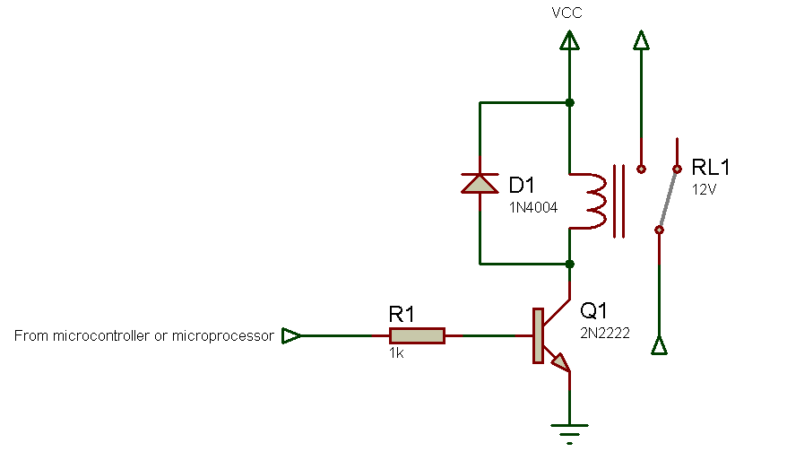
I have to ask, why are you using a relay to control a solenoid rather then just control the solenoid directly with a transistor or driver rated to be able to handle the voltage and current requirement of the solenoid? Then, share your views, comments, ideas, and suggestions by posting in the comments section below. I have posted a project on green house system in which relay driver circuit using uln2003 is used to drive four relays. The microcontroller provides high or low input signals to npn i have posted a project on the greenhouse system in which the relay driver circuit using uln2003 is used to drive four relays. The relay driver circuit using an npn transistor is given below. Relay driver circuit using transistor relay driver circuit using npn transistor is given below. Advantages of the low side driver. The uln2803 ic consists of eight npn darlington pair which provides the proper current amplification required by the loads. Hi, i need to use relay drivers for my project. As an alternative to using discrete transistors, special purpose driver ics are also available that can drive multiple devices. Led series and parallel connections. This module also includes general purpose i/os, and analog. You can calculate the power saved as shown below:
Relay driver 6 this section details two software installation options. Relay drive by means of scr. Far more interface options including the popular uln2003 driver. When the circumstances make the use of this connection unavoidable, if the voltage is not completely impressed on the relay, the transistor does not conduct completely and operation is. When using logic signals to control a relay, a driver circuit must be used to boost the current needed to energize the relay's electromagnetic coil.
How To Make Relay Driver - miliohm.com from miliohm.com Here we will learn how to correctly operate a relay using a transistor and apply the design in electronic system for switching a connected load without issues. We must need an external circuit to drive relays with stm32 this post is about teaching you what must be used with stm32 microcontroller to driver multiple relays with it. A relay driver circuit is a circuit which can drive, or operate, a relay so that it can function appropriately in a circuit. I have to ask, why are you using a relay to control a solenoid rather then just control the solenoid directly with a transistor or driver rated to be able to handle the voltage and current requirement of the solenoid? Simple coding in a language i already use. Relay drive from external contacts. Last updated on january 22, 2020 by swagatam 60 comments. So if you want the high signal to turn on the relay, use the normally open terminal
The uln2803 ic consists of eight npn darlington pair which provides the proper current amplification required by the loads.
This product has four onboard relays and associated drivers capable of controlling a variety of devices including lamps, motors, locks etc… (please see recommendations for using this product with inductive loads elsewhere in this document). We all know that the transistors are used to amplify the current but here darlington transistor pairs are used inside the ic to make the required. The driven relay can then operate as a switch in the circuit which can open or close, according to the needs of the circuit and its operation. Relay driver circuit using transistor relay driver circuit using npn transistor is given below. Msview is also used to configure and program the relay driver. So if you want the high signal to turn on the relay, use the normally open terminal The relay drive circuit should be designed for 3 volts, not the set voltage. And generally relay coils are designed to operate from a particular supply voltage often 12v or 5v, in the case of many of the small relays used for. When the circumstances make the use of this connection unavoidable, if the voltage is not completely impressed on the relay, the transistor does not conduct completely and operation is. Advantages of the low side driver. Fan relay relay on your 1994 pontiac sunbird, the relay is: The microcontroller provides high or low input signals to npn i have posted a project on the greenhouse system in which the relay driver circuit using uln2003 is used to drive four relays. Under hood, driver side, front engine area.